Geometry
The general purpose of any bridge
is to span a distance horizontally. In
the case of the towers, cables and deck
the cables are the simplest and will therefore
be used to begin the study of spanning structures.
Below are some diagrams of the bridge with dimensions and identifications. The first diagram shows the longitudinal elevation of the bridge.
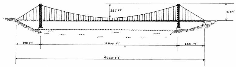
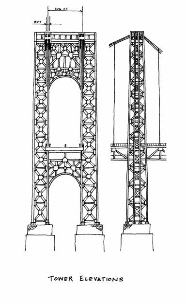
The left approach span is shorter than the right one: 610 feet as opposed to 650 feet. For simplicity, the analysis will assume that both are 650 feet and treat the bridge as a symmetrical structure. The middle span is 3500 feet, and the sags of the cables are 327 feet in the middle and 377 feet at the sides. The following set of diagrams show two elevations of the tower. There are two cables of three feet diameter on each side of the bridge. The centers of each pair are nine feet apart and the pairs themselves are 106 feet apart.
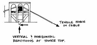
These cables are idealized as supported by rollers at the top of the towers. This means the horizontal components of force in each side of the cable must be equal.
The cables support the roadway, i.e., the road deck is hung by suspenders attached to the cables. The cables are made of 26,474 steel wires, each 0.196 inches in diameter. Each wire, therefore, has an area of:
Then each cable has an area of:
With four cables a total area of is supporting the loads of the deck and the
traffic. The cables are continuous over
the tower supports and are firmly anchored into both banks by huge blocks of
concrete
the anchors.
Because the cables are so much longer than they are thick and are made up of many small wires, they can be idealized as perfectly flexible, like a length of string. The actual cables are quite flexible, although not perfectly. A flexible structural element can resist only axial tension forces; it cannot resist compression, shear or bending.
The tower supports of the bridge are 578 feet tall and rest on concrete caissons (supports) in the river. This analysis will assume that the towers will be subjected to only vertical loads because the cables are supported by rollers and cannot transmit any horizontal forces to the towers. Since the main point of this analysis concerns the structural behavior of the cables, no particular attention will be given to the towers.
Introduction Geometry Loads Reactions Internal Forces Stresses Efficiency Explore